Portable dbx Encoder/Decoder
PG-NR-02, a 9 V battery-powered dbx Type II encoder/decoder with a discrete electret microphone preamp, built around the Panasonic AN6291 to bring dbx noise reduction to portable cassette recorders like the Sony WM-D6C. Open hardware, designed in KiCad.
Why
I tape live concerts on cassette. The Sony WM-D6C has a good transport and is small enough to go unnoticed, but it only offers Dolby B and C. dbx Type II gets far more dynamic range out of a cassette, and the outboard dbx units that exist are mains-powered home or studio boxes. I wanted a pocket unit that takes electret microphones directly, encodes dbx II and feeds the line input of the recorder, running from a single 9 V battery.
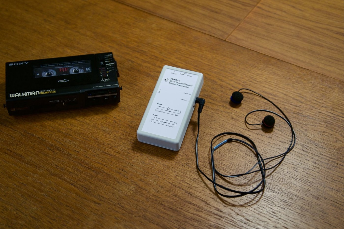
How dbx II works, and what that means for the circuit
dbx is a broadband 2:1 compander. On encode, the signal is pre-emphasised and compressed 2:1 in dB around a reference level; on decode, it is de-emphasised and expanded 1:2. Tape noise picked up between the two is pushed down by the expansion, which is where the large noise reduction comes from. Unlike Dolby B/C, which only work on the high-frequency band, dbx acts across the whole spectrum.
The same mechanism sets the design priorities:
- Any error recorded on tape is doubled in dB on playback. Distortion and level errors from the encode chain or the tape come back amplified, so the analogue path around the compander has to be clean.
- The encode and decode filter networks must match the dbx II curves. The AN6291 datasheet application circuit defines them, and there is very little freedom in those values. I kept them as specified.
- The compander tracks absolute level. Each unit is adjusted for its own AN6291 with the on-board trimmer.
Circuit
The core is the Panasonic AN6291, a discontinued dual-channel dbx II IC from the 1980s that contains both the encode and decode paths. Around it:
- Electret microphone preamplifier. A discrete preamp per channel (KSC1845 input transistors, with BC848 and BCV62 transistors in the support circuitry). The resistor values follow the original preamp schematic it is based on; nearest E96 values can be substituted.
- Microphone bias from the battery. In revision B of the encoder I removed the regulator for the microphone supply and powered the capsules from the 9 V battery directly, which lowered the noise.
- Line-level buffering with OPA1612 op-amps.
- Signal-path capacitors are only C0G/NP0 ceramics or solid tantalums. X7R and X5R ceramics change capacitance with applied voltage, which produces distortion. In a compander that distortion is then expanded on decode, so I avoided them anywhere the audio passes.
- Inputs and outputs: separate mic and line inputs, a line output, a power switch and a fuse on the battery input.
Both boards are designed in KiCad and assembled by hand; revision 2 is a four-layer PCB.
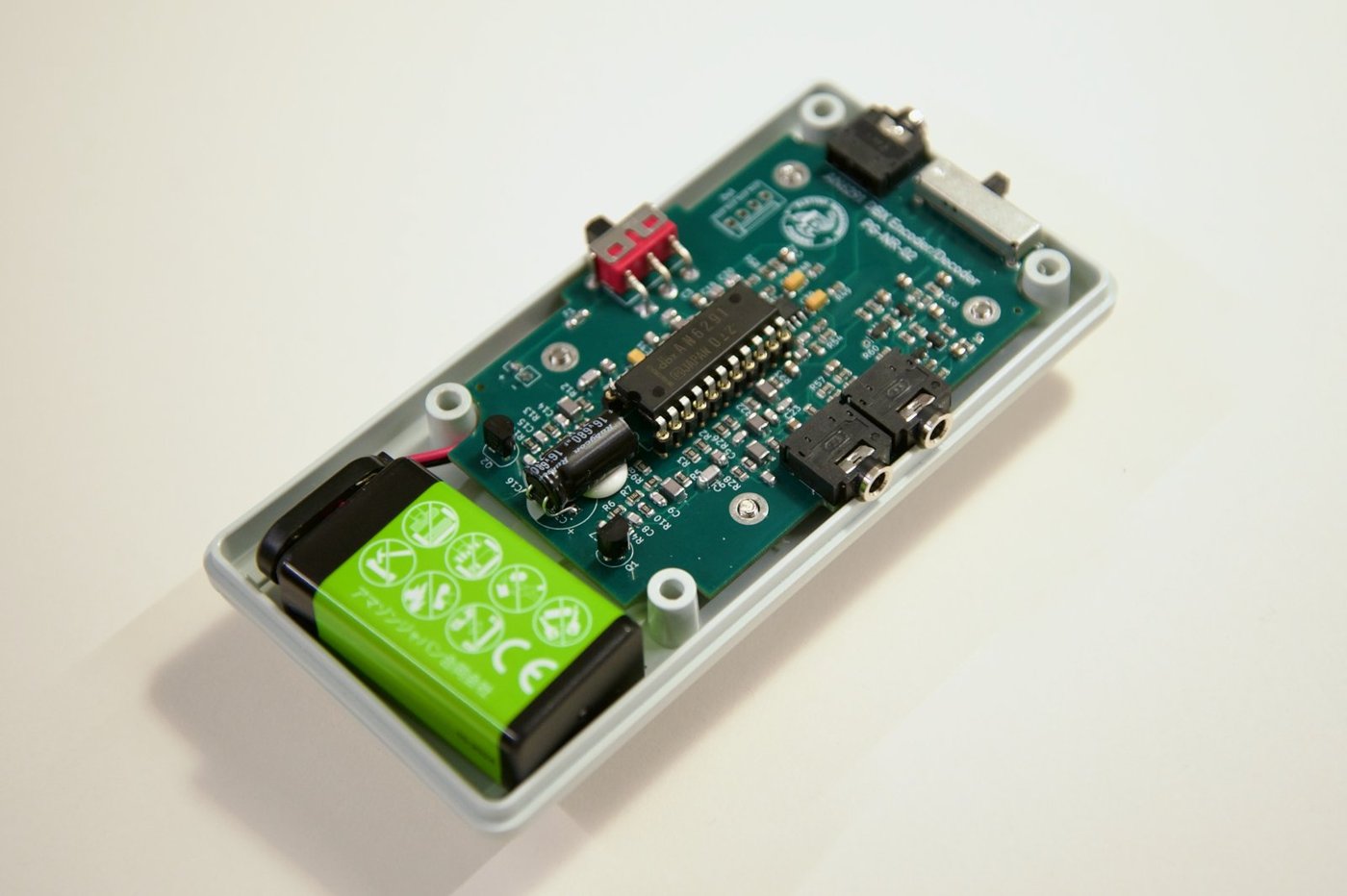
Revisions
Revision 1, encoder only. No mode switch, on purpose: the unit is always in a known state, which matters when setting up in a dark venue. Signal chain: mic in, preamp, dbx encode, line out to the recorder. Line in can also be encoded.
Revision 2 (PG-NR-02), encoder and decoder. An encoder alone still needs a dbx deck or outboard decoder to play tapes back. Revision 2 adds a six-pole slide switch (EG6201) on top of the unit that reroutes the AN6291 between modes:
- Encode: Mic in, preamp, encoder, line out. Or line in, encoder, line out.
- Decode: Line in from the recorder, decoder, line out.
Status and known limitations
I use the unit for my own concert recordings and hand-assemble small batches on demand. Things to know:
- It is not a headphone amplifier. The output is line level and needs to feed a line input.
- The decode input has no attenuation. On encode, the line input handles about 3.5 V peak. On decode, the expander doubles the input level in dB, so a typical line output from a deck can drive it into clipping. A source with a volume control solves it; on the WM-D6C the headphone output is a better feed than the line output.
- Fix without a volume control: a 10 dB inline attenuator, 1.5 kΩ in series and 680 Ω to ground per channel, built into the plug at the unit end so the cable runs at low impedance (about 470 Ω source). Because of the expansion, 10 dB less at the input gives 20 dB less at the output; tracking is unaffected and the level is made up downstream.
- Planned fix: the EG6201 has a spare sixth pole, so a future revision can switch a divider into the decode input only (4.7 kΩ series, 2.2 kΩ shunt), leaving the encode path untouched.
Setting record levels
dbx is forgiving if you record low and unforgiving if you record hot. Too low, around -40 dB, and the noise floor audibly breathes with the music. Too hot, and tape saturation is expanded on playback together with flattened peaks. The WM-D6C meter shows nothing below its -10 dB LED, so I set the gain so that peaks during an average passage of the concert just light that LED.
Schematic and board
The schematic and PCB are shown below in an interactive viewer. You can pan and zoom, select symbols and footprints, and switch layers. The files are read straight from the public GitHub repositories.
Revision 2, encoder and decoder
Revision 1, encoder only